As in most things in CAD or Civil, there are a lot of ways to come to the same result.
For a roads cross slope we have e.g. Civil 3D's superelevation. But what if the road has more than four lanes? The superelevation has options for left and right inside and outside lane, and of course you can also use the shoulders as superelevation (if the shoulders are not used in the superelevation curve manager to have their own slope) but then you may need to keep track of what is what.
Naviate have a solution for you, and you don’t even need to have a lot of lanes to use the Naviate Settings. This solution can be used regardless of how the road looks. It can also be used for other types of transitions or other types of values that you want to have control over along a corridor.
So how does it work?
1. Subassembly
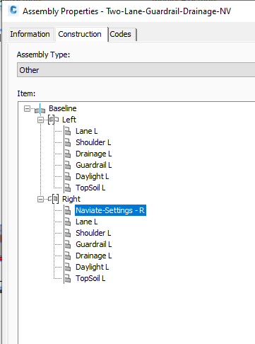
Insert the subassembly Naviate Settings to your assembly. Make sure the Naviate Settings subassembly is inserted before the subassembly you want to control with the Naviate Settings subassembly. What I mean with inserted before is the order of the subassemblies as can be seen in Assembly Properties. You also need one of each side.

2. Parameters
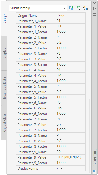
The parameters for the Naviate-Settings can be a bit intimidating at first sight. There are 9 different parameters available. The rows that are named Name is just for yourself to keep track of which parameter is which. Value is where you put in your slope values and Factor is what’s multiplying the Value. If you want to have a slope that is 2.5%, you need to write 0.025. Instead of writing all the zeros for the slope you can write 2.5 as value and 0.01 as Factor.

3. Transitions
So how do you do transitions then? It works like this for the Value parameter: A1,B1|A2,B2 etc, where A is the station value and B is the slope at that station. Then you separate stations and slopes with a vertical line, and on it goes. So if your slope should transit from 2.5 to 5 from station 0 to 10, then it will look like this; 0,2.5|10,5.
What will happen after station 10 if we use it like this? It will keep the value 5, so keep writing the stations and slopes separated with a comma and a vertical line.
4. Slope Values
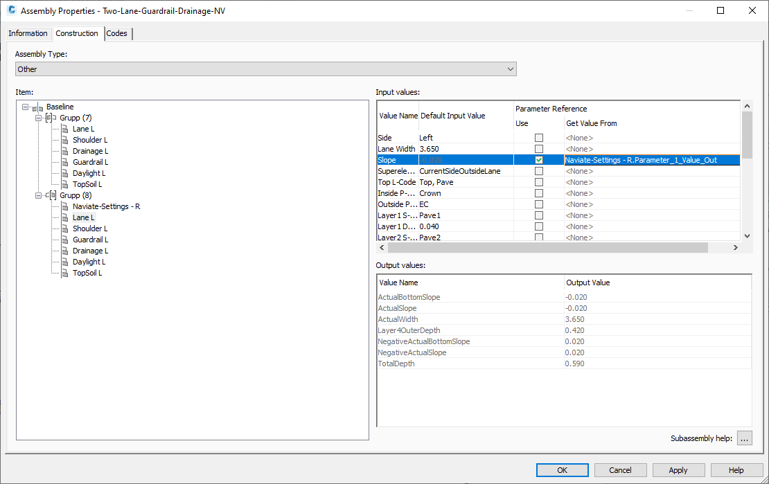
When the slope values are in order, the next step is to connect the values to the correct subassembly. In Assembly properties you need to connect the slope of the Lane to the correct Parameter Value, so if you wrote your slope numbers in Parameter_1_Value, this is the row that you will connect here.

5. Rebuild
Almost done! The heavy work is finished, all you need to do now is rebuild your corridor and check your slopes.
P.S. the vertical line can be made by holding down the button where you find the vertical sign+ctrl+alt. On my computer I find the vertical line sign on the same button as the less or more than signs <>.
Want to know more?
- Want to test it out for yourself? Download a free trial here
- For more information about the individual commands and to see the Feature-videos for the commands, have a look at Symetri e-learning.


