Naviate offers commands for creating piles, and this guide focuses on building Sheet Piles and Anchors for a pipe trench. You'll learn to create Sheet Piles along a linear object, convert 3D polylines to 2D, adjust elevations, and handle corner adjustments. We'll also cover adding Anchors to secure the wall, including aligning them with the sheet piles, setting intervals, and managing elevations for stability.
Naviate contains several commands to create piles. This blogpost will focus on Sheet Piles and Anchors. This example will show how to create a sheet pile wall along a pipe trench, and to add anchors to hold the wall in place.Sheet Piles
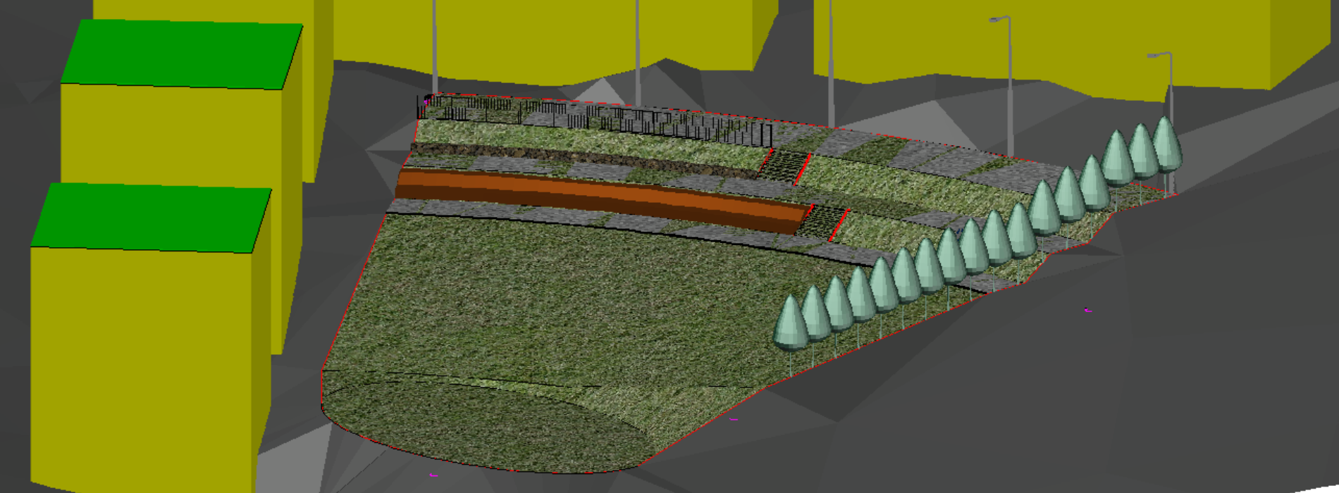
Sheet Piles are created along a linear object. In this example the model contains pipe spans and an alignment. The linear object can be created in any number of ways, for this example Dynamic 3DPoly from Pipe Network is used to create two lines where the sheet pile wall should be placed. To be able to use this one line for all objects in this sheet pile wall, the 3Dpolyline is converted to a 2Dpolyline with Convert3DPolys and then the elevation 140.5 is set on the polyline.

In the dialog a Group name is set, the same name will be used for the other side of the trench wall to keep the objects together.
There is a library of profiles in Naviate, that is accessed via the Profile button. In this case the L600 is selected. Add Profile Blocks is also ticked in this case, which will assist us in solving the corner of the sheet pile wall.
There are multiple ways to handle the elevation of the sheet pile wall, depending on what requirements there are. In this example, the wall will follow the polyline in plan but take the elevation from the surface and be 0.3m above it. The depth is set to be to the Rock-surface.

Once you click OK the sheet piles are created. Now in this example the sheet pile in the corner needs some tweaking to end up in the right position. Since we used Add profile blocks, there is both a solid and a block insert at the corner. The solid is removed, and the block is manipulated with Rotate and Scale and then Sheet Pile from Object is used to create an individual sheet pile.
The dialog remembers the settings from Sheet Pile so automatically the same group name and measurements are used.
The process is repeated on the other side of the trench.

Anchors
When the wall is done it is time to add the anchors. The anchors are created along the same polyline used for the sheet piles. In the dialog the size and interval of the anchors are set. The interval in this example uses Start Station to offset the start point to the middle of the first sheet pile. The interval is set so that an anchor is placed on every fourth sheet pile. The top elevation is set to follow the polylines elevation. The Datum is set to the Rock surface and 1 meter into the rock.
At the bottom Reverse Slope Direction is ticked, this depends on the direction of the polyline. The easiest way to check if this needs to be checked or not is to create the anchors, and if they come out flipped then run the command again and make sure to tick Delete previous anchors in this group to replace the faulty anchors.

If more anchors are needed in the beginning and end, then Create Single Anchors can be used to place individual anchors. The settings are remembered, just remember to untick Delete previous anchors in this group so that these single anchors are added to the group and not replace the entire group.
In this example the option Point is used when placing the single anchors so the Midpoint OSnap can be used to place the anchors. Since the original line determines the placement and the top elevation, it is no problem to OSnap on a spot a bit away from the line, this click only determines the placements distance from the end of the line, but still measured along the line.
In this example, a few single anchors are added in the start, end and around the bend in the middle.

Then the same process is repeated on the other side, only difference is that Reverse slope direction is unticked for this line.
Waling
The final part of the sheet wall is walings to keep anchors in place. These are created with Extrude along path. In the dialog a block can be used and with Browse an UPE-profile can be selected from the Naviate library.
The rotation is set to 315 to match the 45-degree angle of the anchors. The Offset moves the waling along its X-axis which in this case means it is half the diameter of the anchors. The polyline that the waling will follow is in the middle of the anchor.
The tricky part here is the added elevation. The polyline that will be the path is in the middle of the sheet pile wall, but the waling needs to be on the inside of the wall, which means it needs to be moved upwards along its own Y-axis. But it needs to be moved along the anchors, that are at a 45-degree angle to the wall. This requires some math and geometry – or use the Pick option next to Add Elevation. First pick a point on the polyline, then the perpendicular point of the sheet walls inner edge. Use that distance i 2D and divide it by Sin (Rotation) - these are options from the command line. The resulting value is added to the dialog.
To create the bottom part of the waling, note down the Add Elevation-value and create a Flipped version of the same beam.